Feature:
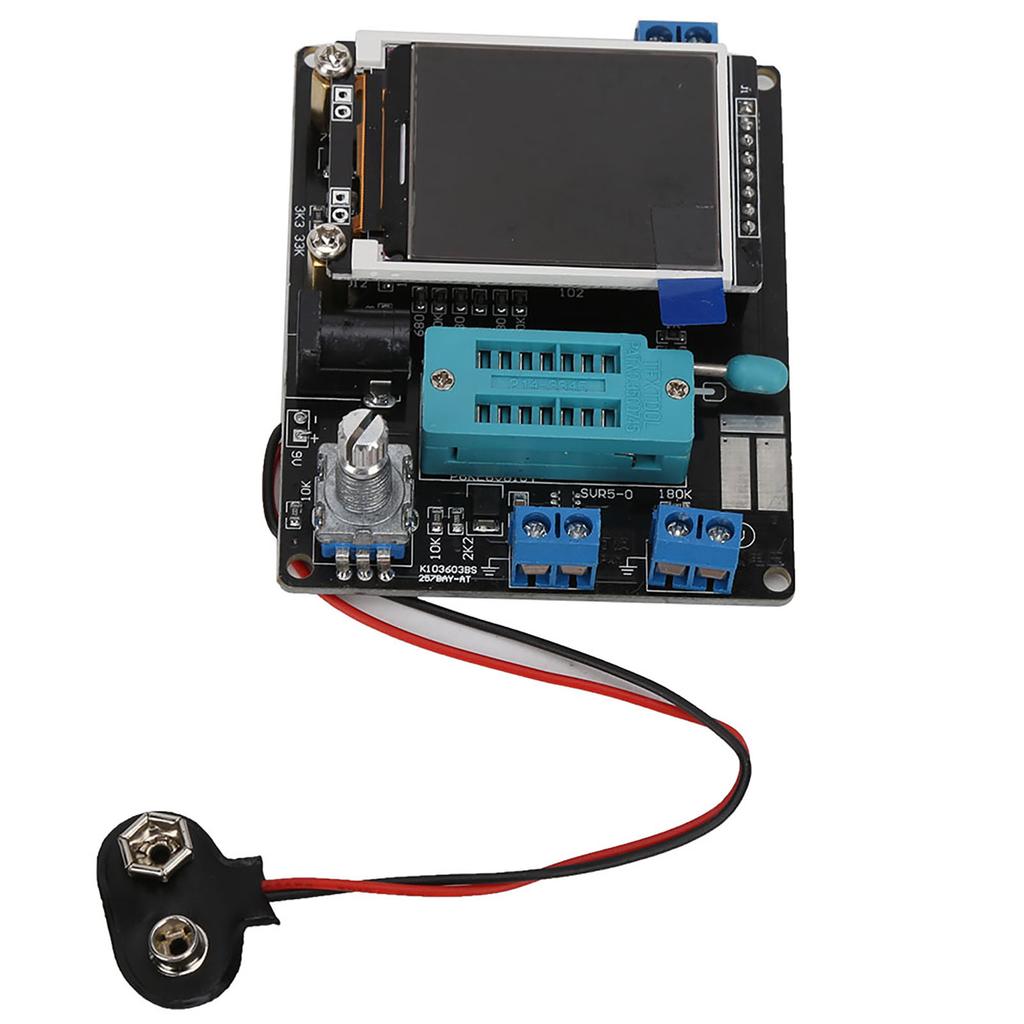
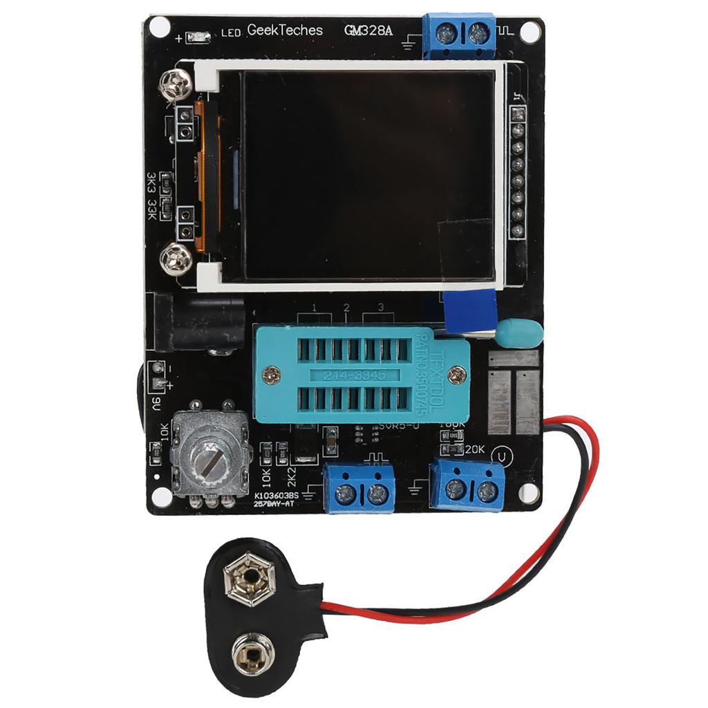
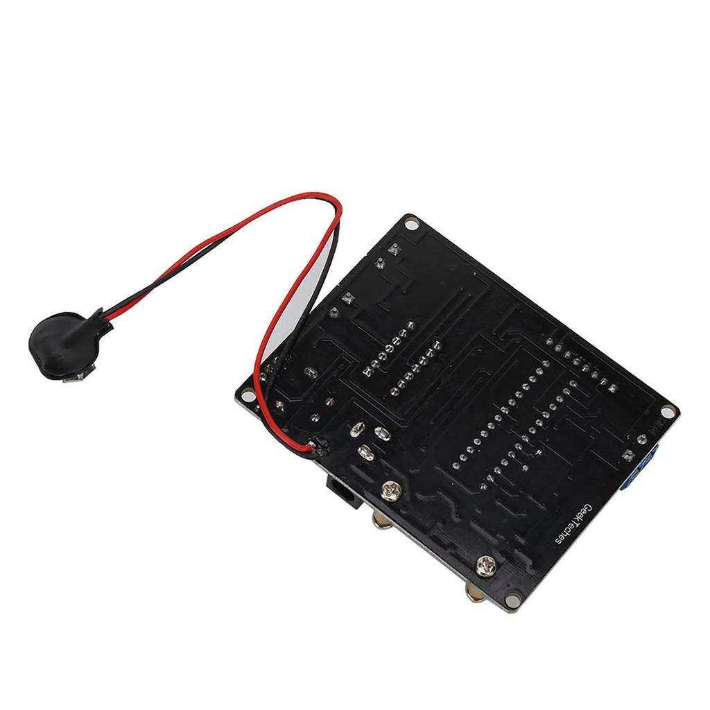
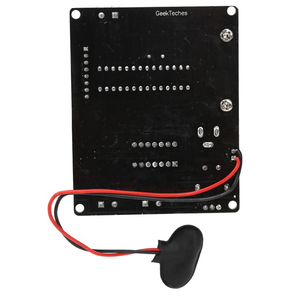
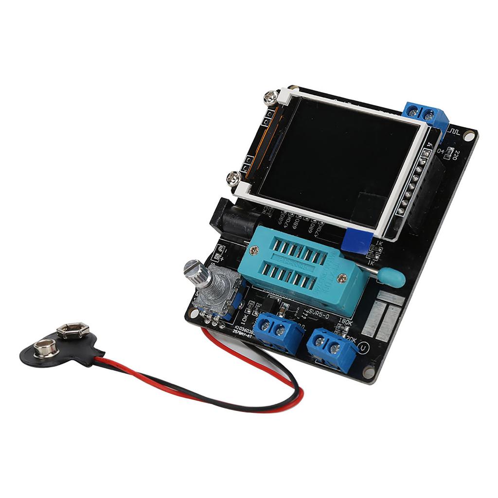
1. The use of single chip microcomputer ATMEAG328P DIP28 with IC block.
2. The display unit uses a 160x128px color display, fullscreen characters 8x20, 16bit color depth, graphic display elements symbols.
3. Rotating coding switch control, onebutton measurement, automatic shutdown.
4. Powered by 9V laminated battery (not included), can also use the power adapter, the whole current of about 30mA, about 20nA current after shutdown.
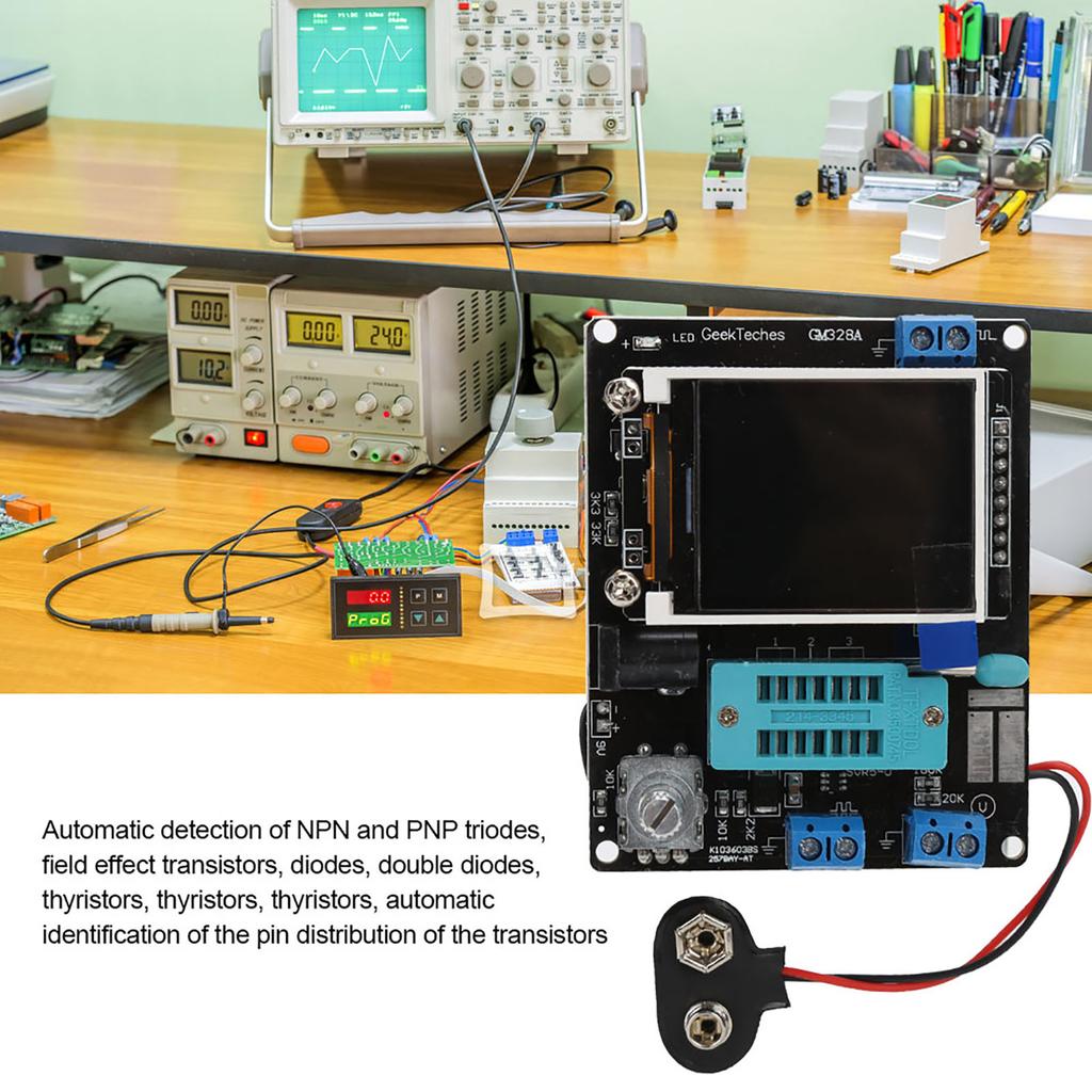
5. Automatic detection of NPN and PNP transistors, FET, diodes, dual diode, thyristor, silicon controlled rectifier, automatic identification of the above transistor pin out.
6. Test NPN and PNP triode common emitter current amplification factor, baseemitter threshold voltage, collectoremitter leakage current at turnoff.
7. Identification for Darlington transistors through triode baseemitter threshold voltage and high current amplification factor.
8. Detect power triode and FET builtin protect diodes.
9. Test FET gatesource turnon threshold voltage, drainsource onresistance, gatesource capacitance.
10. It can measure up to 2 resistors at a time, so the adjustable resistors of the three feet can also be measured. If the adjustable resistor is adjusted to the end point, only one resistance value can be measured.
11. The resistance is measured at a maximum resolution of 0.01 Ohm . Can measure up to 50M Ohm .
12. Capacitor measurement range from 25pF to 100mF with 1pF resolution.
13. For capacitors larger than 90nF, the equivalent series resistance is measured at the same time. The resolution of the equivalent series resistance is up to 0.01 Ohm .
14. For capacitors larger than 5000pF, the voltage drop rate after charging is also displayed. This value can reflect the quality factor (Q value) of the capacitor.
15. Measure up to two diodes at a time, showing their positive and negative, onvoltage.
16. The LED is also shown as a graphical symbol of the diode, which has a much higher turnon voltage than a normal diode.
17. A voltage stabilizing diode with a reverse breakdown voltage lower than 4.5V can also be detected and displayed as a double diode symbol. The positive and negative poles have a diode symbol with a turnon voltage of about 700mV, and the turnon voltage corresponding to the other diode symbol is a regulated value. So don"t measure a normal diode and a voltage stabilizing diode simultaneously.
18. When testing a single diode, the reverse junction capacitance of the PN junction is tested at the same time. The PN junction capacitance of the transistor can also be tested. At this time, only the base and emitter of the transistor, or the base and collector can be placed at the same time.
19. Capacitors below 25pF can also be tested. This test requires first preparing a 30pF capacitor, first testing the 30pF capacitor, then measuring the capacitor to be tested in parallel with it, and subtracting the measured value of the 30pF capacitor from the result.
20. The inductance is measured simultaneously for resistors up to 2100 Ohm , measuring from 0.01mH to 20H.
21. The test process takes about 2 seconds, and large capacitors and inductors take longer.
22. Additional features include frequency measurement, voltage measurement, square wave generator, PWM generator, infrared remote control decoding, infrared remote control code, temperature sensor test, temperature and humidity sensor test, color selection, debug calibration, continuous test, etc.
23. The frequency measurement range is from 1Hz to 1 MHz or higher. When the measured frequency is lower than 25kHz, the period can be displayed with a resolution of 0.001mHz.
24. DC voltage measurement up to 50V.
25. Output one square wave signal, multiple frequency options are available, the highest output frequency is 2MHz.
26. Output a fixed frequency, duty cycle adjustable pulse signal (PWM), duty cycle adjustment from 1percent to 99percent .
27. Separate capacitance test function, the test method is continuous measurement. For 2uF50mF capacitors, it can be directly measured in its circuit. (The circuit where the measured capacitor is located must be powered off, and the measured capacitor needs to be completely discharged.)
28. Thyristors and silicon controlled rectifier can only recognize their pinouts, and also require the thyristor or silicon controlled rectifier to have a lower trigger current than the tester can provide. The tester can only provide up to 6mA of trigger current.
29. Infrared remote control decoding and encoding support encoding formats for TC9012 and for upD6121 chips.
Specification:
Item Type: GM328 Transistor Tester
Material: Plastic
Color: Black
Package List:
1 x Transistor Tester4 x Screw4 x Copper Long Nut
Note:
Always discharge the capacitor before testing the capacitor. Otherwise it may damage the tester"s microcontroller.Please note that the new type and old type of this product will be sent randomly, and make sure you will not mind before ordering.
The use of single chip microcomputer ATMEAG328P DIP28 with IC block.
The display unit uses a 160x128px color display, fullscreen characters 8x20, 16bit color depth, graphic display elements symbols.
Rotating coding switch control, onebutton measurement, automatic shutdown.
Powered by 9V laminated battery (not included), can also use the power adapter, the whole current of about 30mA, about 20nA current after shutdown.
Automatic detection of NPN and PNP transistors, FET, diodes, dual diode, thyristor, silicon controlled rectifier, automatic identification of the above transistor pin out.